So after spending some time debugging and not getting why the new button panel board didn’t work, as it measssured exactly how it should following the schematics, and after basically replacing every TTL chip (I did find some dodgy ones), it was time to start comparing it to the original and soon enough the issue was found.
The original devlopers used a different pin order on the IDC flatcable. Not sure if there were standards for them back then, but now there are that was what was used. A new flatcable constructed out of Ardiuno Jumper wires showed this beautiful image:
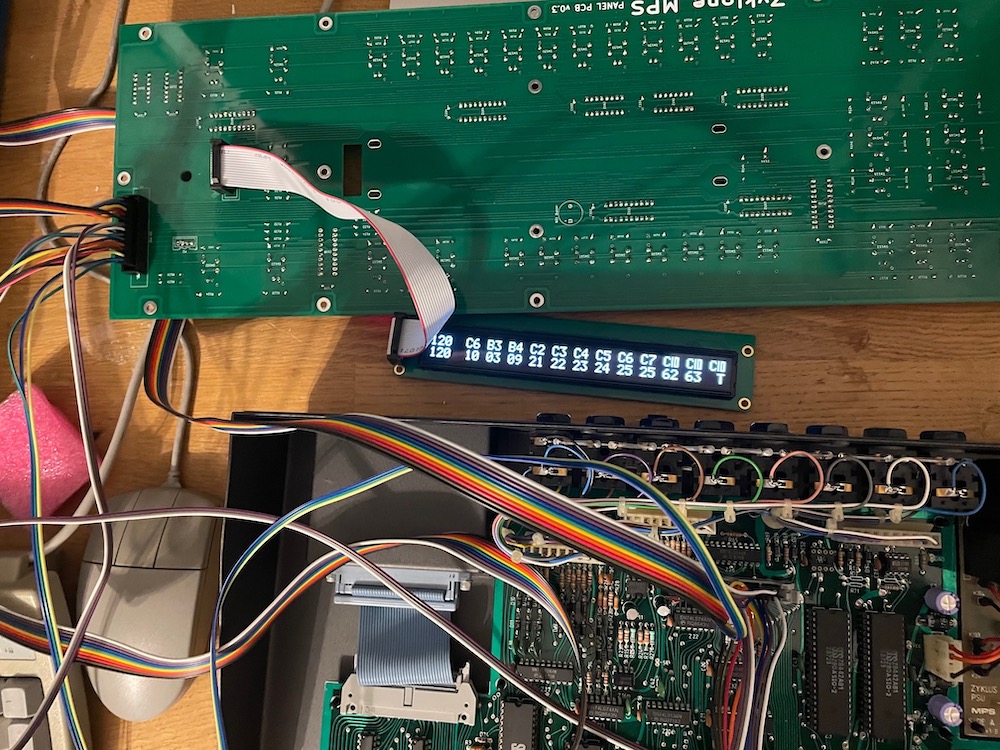
All buttons and LED’s work as they should. So does the buzzer. I’m attaching the encoder later, but I have no doubt it will work too.
With that, the power PCB and the panel PCB are done. There is a revision coming of the panel PCB, but that is to clear up a small layout issue and one trace error for which I now use small jumpers.
Onto the mainboard!