It took a fair bit of time to get to this point, but here we are..
Going step by step to the various repairs.
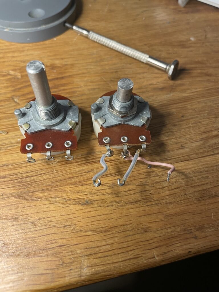
First off was the encoder. This one was pretty much completley stuck, but with some grease it started moving again. Not fluent enough though to keep, so I replaced it with one of my spares.
Replacement Encoder
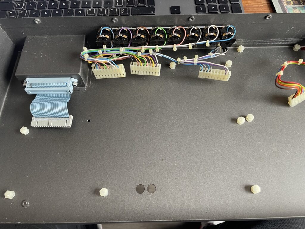
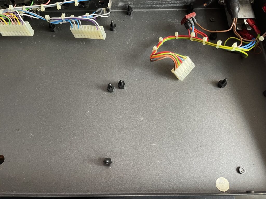
Next up where the mainboard nylon standoffs. They were all broken. I ordered new ones, these came in black. Easy enough repair.
Broken standoffsNew standoffs
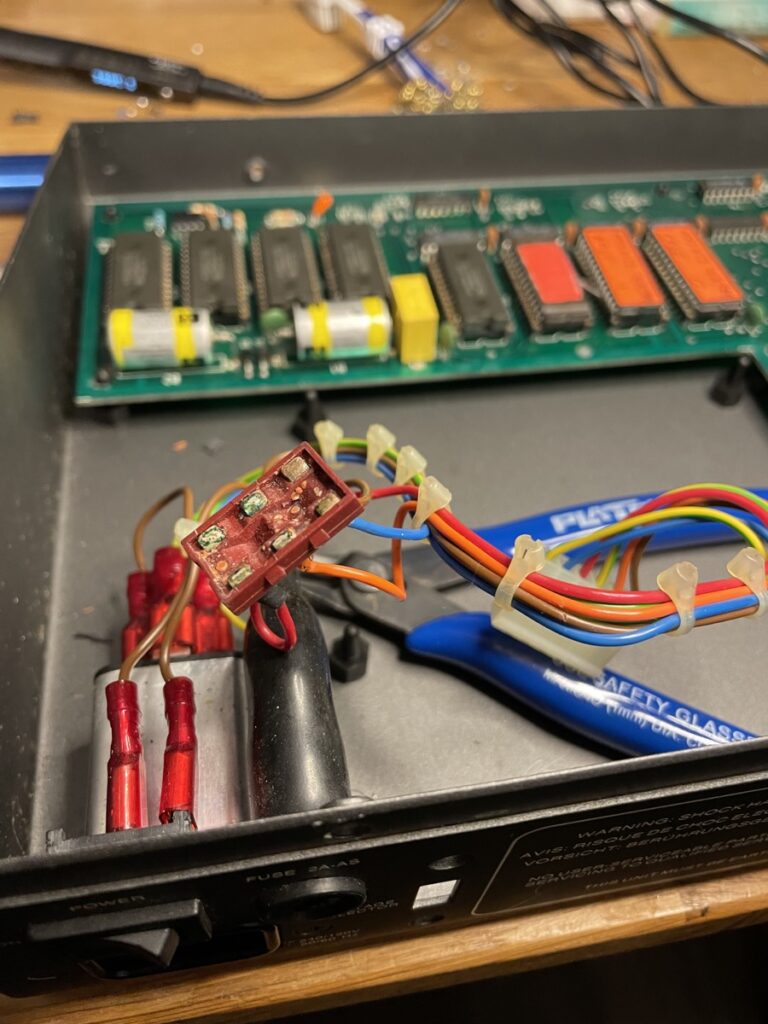
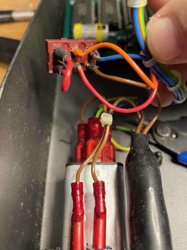
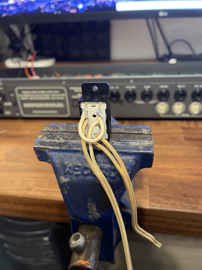
Then it was time to tackle the voltage selector. It needed replacement.
At first I simply tried to resolder it using the existing wiring, but they were so degraded that it became such a hassle to do that I decided to rewrire the whole thing.
Next up was the display.
I don’t have pics of the process, but it boils down to desoldering the display including header (thats easier), removing the inverter and transistor, installing a new header and adding the OLED.
And here’s where the fun began:
Everything worked except for 5 buttons which where on the same colum in the matrix. I tested continuity as far as possible, but no issue found.
I replaced a few switches to no avail. So I desoldered the TTL on which they terminated and replaced it (on a socket). No difference, so the TTL was good.
Then I wanted to do more continuity testing, which involved removing more switches and the flatcable conntector. Which was very hairy, because due to the condition of the board, traces came off like snowflakes.
More testing, no issue found… so on to repair the tracec that got damaged during desoldering, all put back together and I was ready to pull my hair out.
Every now and then, one of the ‘broken’ buttons would trigger though, especially when I was handling the board – somethig a cold solder joint would do. So I reflowed EVERYTHING. Still no difference.
User Panu told me he once had his display replaced by an OLED, like I did, which resulted in not working keys. His tech told him that the OLED was incompatible, different pinout etc. Which I found weird. The pinout is exactly the same as it is an industry standard,
the OLED is compatible and I succesfully replaced it on the Vangelis machine too.
I did notice that the other end of the matrix terminated at one of the LCD data pins. Then it dawned on me, the underside of the OLED is different vs the original LCD unit. The metal tabs are on different places, what if it touches something, like a via or trace where the laquer is gone?
So I losened up the bolts, put some paper underneath it and presto… problem solved.
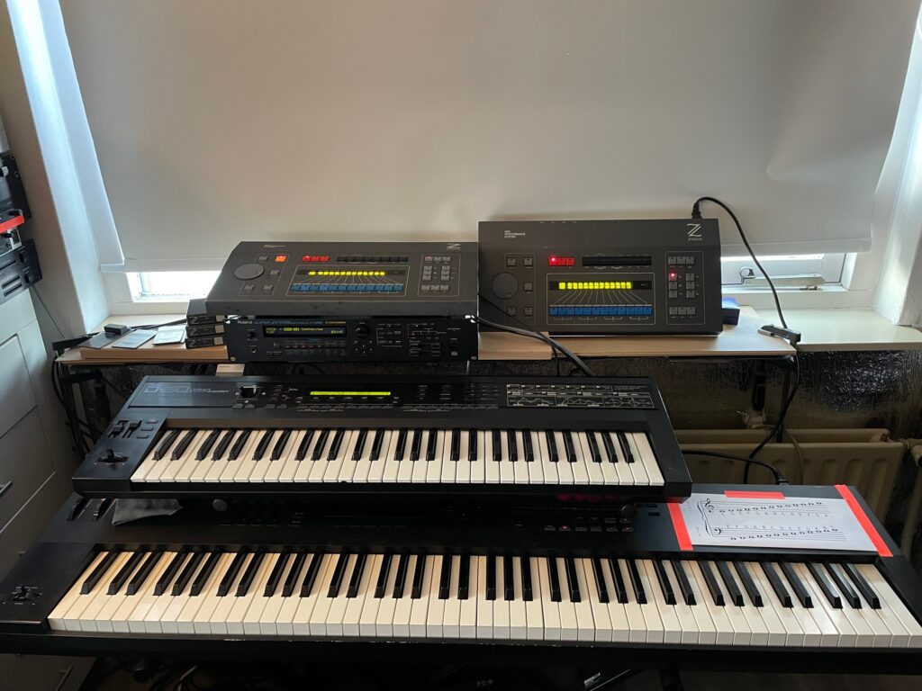
Machine fully functional. I could replace the buttoms with the originals again, but at this point I’m very weary to keep desoldering stuff on this thing. The humidity did a number on this box and the switch board is very fragile.
If we get to the point where we have working replacement prints, I’ll desolder everything and rebuild on a replacement board.