I found some OLED 40×2 for a reasonable price and ordered a couple. Onto the surgery to replace the unit.
First step is to remove the inverter and transistor – they are no longer needed. That’s the easy part.
The hard part is to remove the display. These boards are pretty old, the solder as well and any pad will lift real easilly if heated to long.
I therefore opted to sscrifice the old LCD unit by carefully clipping the board away surrounding the header pins. This allowed me then to remove the header pins one by one.
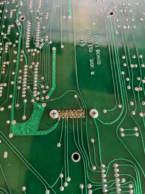
It’s a two-sided board so the through-holes needed to be carefully cleaned out, using a lot of wick and a good solder sucker.
This is a long process done with a lot of care, because these pads are extremely fragile.
Once nicely clean, we can install the display and this was the point where I discovered I didn’t have any headers left…. so I had to order new headers and wait for them…

Well, a few days later actually, the headers came in and I installed one on one of the OLEDS:
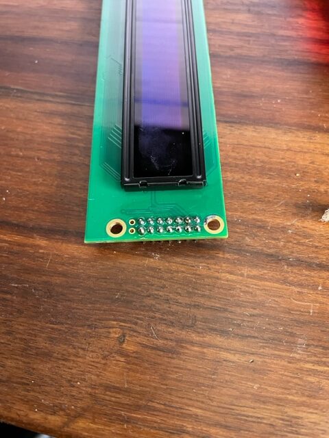
The key here is to not spare the flux… (I use Amtech soldeer flux NC-559-ASM-UV).
With the new header installed, the display neatly fits over the existing standoff screws:
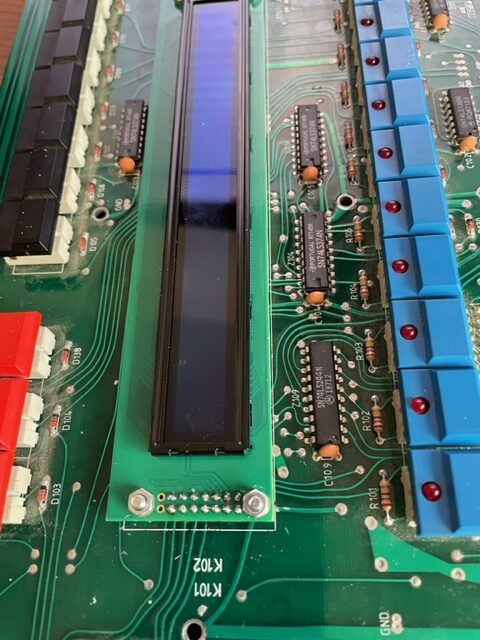
After soldering the switchboard side, and doing continuity tests for every available lead, the install is ready for testing:
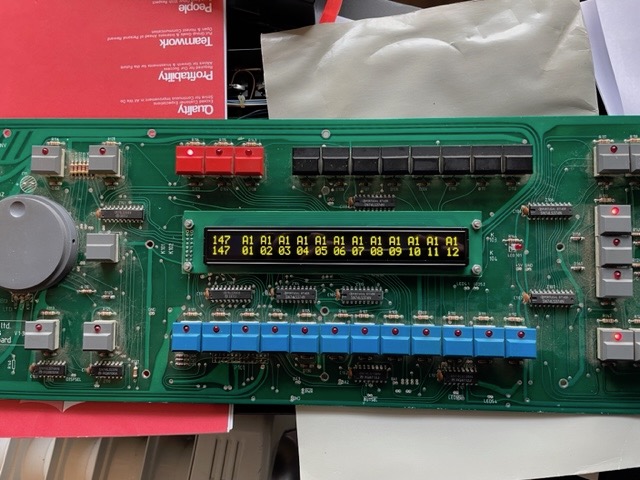
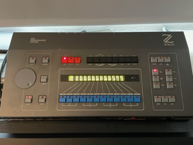
Everything works, so installing the board and case back together and we have new display running 🙂
It looks a bit hazy in the picture but in reality is’ts crystal clear from any angle, really nice!