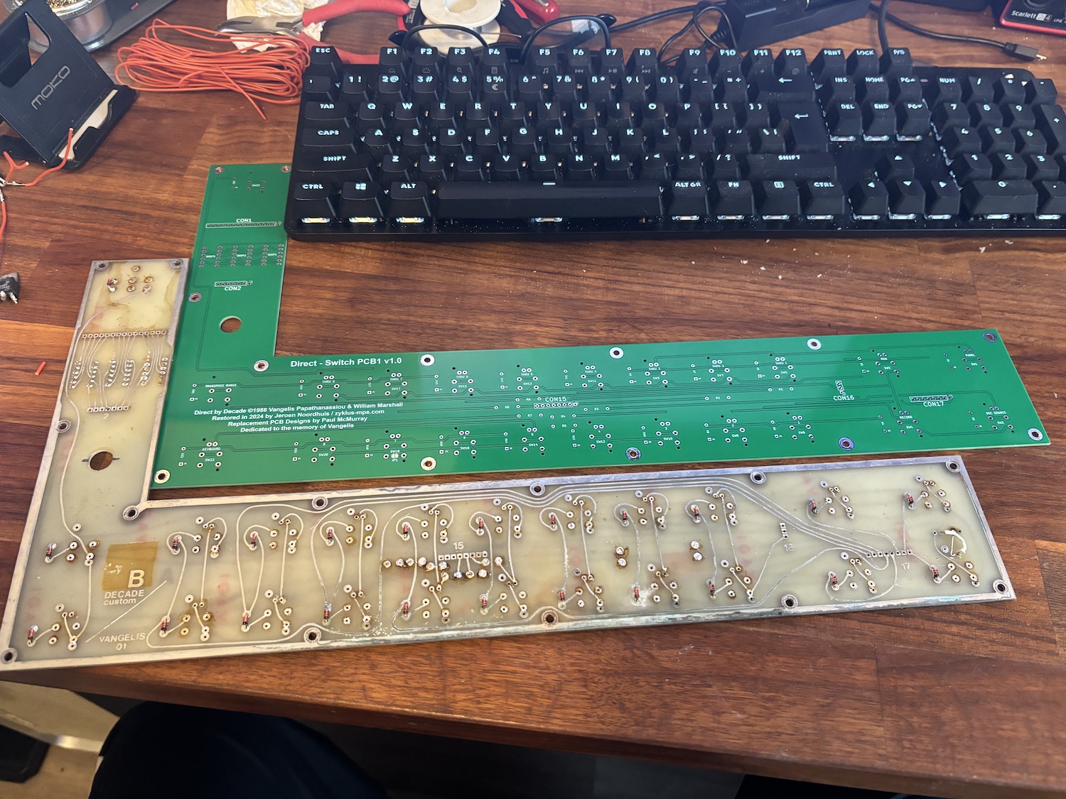
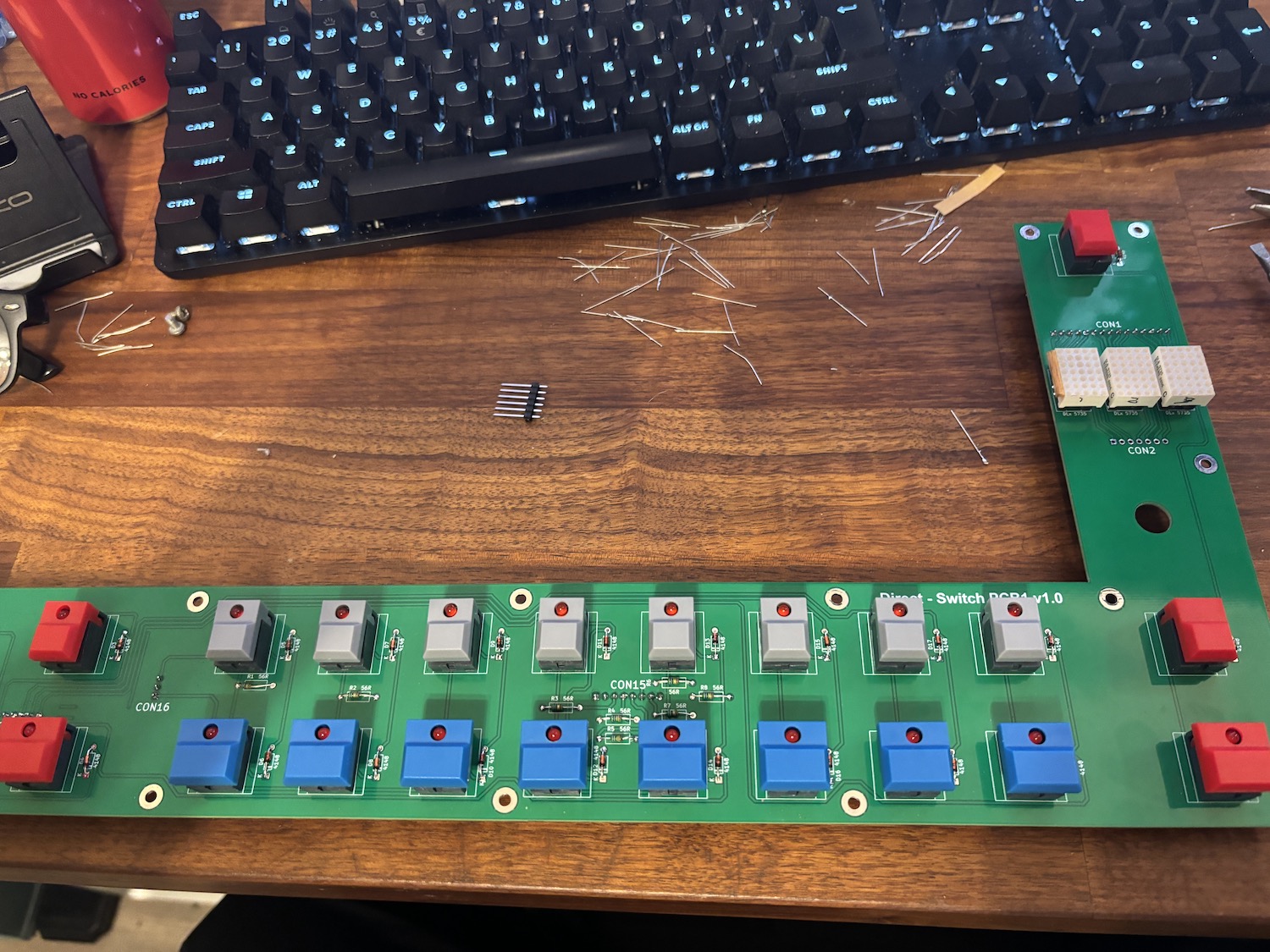
That was a really quick turnaround! Here’s the new switchboard.

I build it up with the switches, diodes, resistors and new extra long header pins.

A test fit to the front panel showed that it was nearly perfect. Only the lower row could use a nudge (less than 1 mm) up and the upper right red switch was off by a mm as well. Everything else was perfect, including the display units.
I’m crazy impressed with Paul’s work.
This weekend I will do a comparative continuity test of the old and new board, but I don’t expect any differences.
Other things cooking: I’m rebuilding the power supply. It had a broken voltage regulator. While it isn’t anything exotic, the way it was build was a bit interesting.
There are 2 separate 5v regulators of different types. Then there is a 5v lead coming from one of the rectifiers. And finally there is a +12.
They were soldered to pins on the main board, I will replace that with a proper connector. Also, eventually, I want to move everything to a proper power supply PCB. Right now it’s just a soldered chain of components.
Bunch of parts were delivered:
– Additional resistors I need for restoration
– Tons of fresh tantalums to replace a few of the more delicate ones
– An EDAC male connector, for the midi breakout box (a seperate one for the audio ports will come later)
On order:
– Tons of m3 screws and stuff in various sizes.
– specific diodes
I’m preparing a few EPROMS. The first one contains simple boot initialization code for the Motorola CPU and the Duarts and will sound a 3 x 3 beep.
Then there will be a more extensive diagnostics EPROM – more on that soon.