(Written by David Perbal)
When we started assembling our Zyklus clones, we realized how complex it would be to upgrade the hardware (based on a Z80) and the software written in assembly language.
Just take a look at the PCBs needed for the ReZyklus :
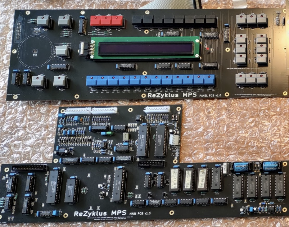
Especially since we couldn’t find the toolchain to compile the old assembly code for rewriting EPROMs. So, the idea quickly emerged of perhaps developing a V2 based on modern, simplified hardware and a software layer that was easy to write, compile, and maintain.
After much discussion and experience with other projects, we chose the Teensy 4.1 microcontroller.
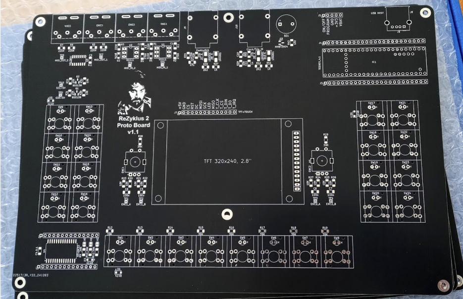
At the end of 2024 I spoke about this V2 with Paul, our electronics wizard. Rather than embarking on “spaghetti” breadboard projects, I suggested building a prototype PCB to validate the hardware choices and confirm that we could indeed achieve our desired functionality. Paul recommended using the HT16K33 chip, which can scan up to 39 buttons in a single scan and control up to 128 LEDs. So the prototype PCB includes:
- a Teenzy 4.1 microcontroller
- a HT16K33 chip
- a 2.8″ resistive touchscreen
- three rows of eight buttons, each associated with an LED
- two rotary encoders
- two MIDI IN and two MIDI OUT ports
- a buzzer
- a footswitch jack input
- a jack input for an external clock
- a USB host port
I ordered the PCBs and here’s what it looks like :
After soldering the components and writing some code to test them, it immediately becomes much more enjoyable 🙂
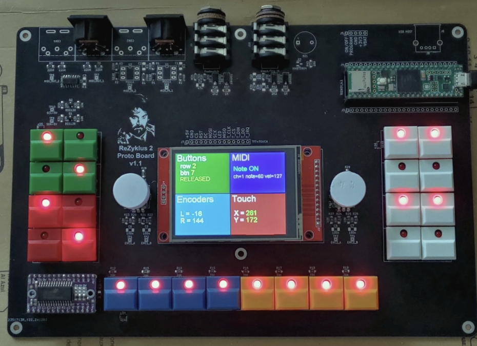
Here I used the same “vintage” buttons as on the ReZyklus V1.
But then I realized that a 2.8″ touchscreen was really small, and the resistive touch wasn’t very responsive. So I looked for another solution.
To be continued…
David